![]()
What is Reverse Osmosis?
Reverse Osmosis is a technology that is used to remove a large majority of contaminants from water by pushing the water under pressure through a semi-‐permeable membrane. This paper will attempt to explain the basics in simple terms that should leave the reader with a better overall understanding of Reverse Osmosis technology and its applications.
This paper covers the following topics:
- Understanding Osmosis and Reverse Osmosis
- How does Reverse Osmosis (RO) work?
- What contaminants does Reverse Osmosis (RO) remove?
- Performance and design calculations for Reverse Osmosis (RO) systems
- Salt Rejection %
- Salt Passage %
- Recovery %
- Concentration Factor
- Flux Rate
- Understanding the difference between passes and stages in a Reverse Osmosis (RO) system
- 1 stage vs 2 stage Reverse Osmosis (RO) system
- Array
- Reverse Osmosis (RO) system with concentrate recycle
- Single Pass vs Double Pass Reverse Osmosis (RO) systems
- Pre-treatment for Reverse Osmosis (RO)
- Fouling
- Scaling
- Chemical Attack
- Mechanical Damage
- Pre-‐treatment Solutions for Reverse Osmosis (RO)
- Multi-Media Filtration
- Micro Filtration
- Antiscalants and scale inhibitors
- Softening by ion exchange
- Sodium Bisulfite (SBS) injection
- Granular Activated Carbon (GAC)
- Reverse Osmosis (RO) performance trending and data normalization
- Reverse Osmosis (RO) membrane cleaning
- Summary
Understanding Reverse Osmosis
Reverse osmosis, commonly referred to as RO, is a process where you remove a large portion of dissolved solids and other contaminants from water by forcing the water through a semi-permeable reverse osmosis membrane.
Osmosis
To understand the purpose and process of Reverse Osmosis you must first understand the naturally occurring process of Osmosis.
Osmosis is a naturally occurring phenomenon and one of the most important processes in nature. It is a process where a weaker saline solution will tend to migrate to a strong saline solution. Examples of osmosis are when plant roots absorb water from the soil and our kidneys absorb water from our blood.
Below is a diagram which shows how osmosis works. A solution that is less concentrated will have a natural tendency to migrate to a solution with a higher concentration. For example, if you had a container full of water with a low salt concentration and another container full of water with a high salt concentration and they were separated by a semi-‐permeable membrane, then the water with the lower salt concentration would begin to migrate towards the water container with the higher salt concentration.
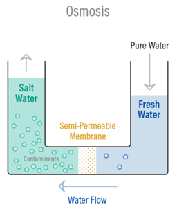
A semi-‐permeable membrane is a membrane that will allow some atoms or molecules to pass but not others. A simple example is a screen door. It allows air molecules to pass through but not pests or anything larger than the holes in the screen door. Another example is Gore-‐tex clothing fabric that contains an extremely thin plastic film into which billions of small pores have been cut. The pores are big enough to let water vapor through, but small enough to prevent liquid water from passing.
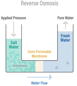
Reverse Osmosis is the process of Osmosis in reverse. Whereas Osmosis occurs naturally without energy required, to reverse the process of osmosis you need to apply energy to the more saline solution. A reverse osmosis membrane is a semi-‐permeable membrane that allows the passage of water molecules but not most of the dissolved salts, organics, bacteria, and pyrogens. However, you need to ‘push’ the water through the reverse osmosis membrane by applying pressure that is greater than the naturally occurring osmotic pressure.
Below is a diagram outlining the process of Reverse Osmosis. When pressure is applied to the concentrated solution, the water molecules are forced through the semi-‐permeable membrane and the contaminants are not allowed through.
How does Reverse Osmosis work?
Reverse osmosis works by using a high-pressure pump to increase the pressure on the salt side of the RO and force the water across the semi-‐permeable RO membrane, leaving almost all (around 95% to 99%) of dissolved salts behind in the reject stream. The amount of pressure required depends on the salt concentration of the feed water. The more concentrated the feed water, the more pressure is required to overcome the osmotic pressure.
In very simple terms, feed water is pumped into a Reverse Osmosis (RO) system and you end up with two types of water coming out of the RO system: good water and bad water. The good water that comes out of an RO system has most contaminants removed and is called permeate. Another term for permeate water is product water. Permeate is the water that was pushed through the RO membrane and contains very little contaminants. RO system sizes are based on permeate flow. A 100 gpm RO system implies that the RO system will produce 100 gpm of permeate water. The ‘bad’ water is the water that contains all the contaminants that were unable to pass through the RO membrane and is known as the concentrate, reject, or brine. All three terms (concentrate, reject, and brine) are used interchangeably and mean the same thing. The following has a simple schematic that shows water flows through an RO system.
As the feed water enters the RO membrane under pressure (enough pressure to overcome osmotic pressure) the water molecules pass through the semi-‐permeable membrane and the salts and other
contaminants are not allowed to pass and are discharged through the concentrate stream. The concentrate goes to drain or can be fed back into the feed water supply in some circumstances to be recycled through the RO system to save water. The water that makes it through the RO membrane is called permeate or product water and usually has around 95% to 99% of the dissolved salts removed from it.
Below is a diagram that shows the water flows through a RO membrane.
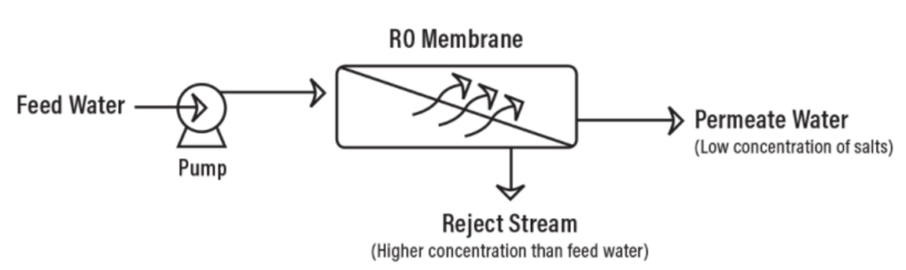
It is important to understand that an RO system employs cross filtration rather than standard dead-end filtration where the contaminants are collected within the filter media. With cross filtration, the solution passes through the filter, or crosses the filter, with two outlets: the filtered water goes one way, and the contaminated water goes a different route. To avoid a buildup of contaminants, cross flow filtration allows water to sweep away contaminant build up and allow enough turbulence to keep the membrane surface clean.
What will Reverse Osmosis remove from water?
Reverse Osmosis can remove 95-99% of the dissolved salts (ions), particles, colloids, organics, bacteria, and pyrogens from the feed water. An RO membrane rejects contaminants based on their size and charge. Any contaminant that has a molecular weight greater than 200 is likely rejected by a properly running RO system. Likewise, the greater the ionic charge of the contaminant, the more likely it will be unable to pass through the RO membrane. For example, a sodium ion has only one charge (monovalent) and is not rejected by the RO membrane as well as calcium for example, which has two charges.
Therefore, an RO system does not remove gases such as carbon dioxide (CO2) very well because they are not highly ionized (charged) while in solution and have a very low molecular weight. Because an RO system does not remove gases, the permeate water can have a slightly lower than normal pH level depending on CO2 levels in the feed water as the CO2 is converted to carbonic acid.
Reverse Osmosis is very effective in treating brackish, surface and ground water for both large and small flows applications. Some examples of industries that use RO water include pharmaceutical, boiler feed water, food and beverage, metal finishing and semiconductor manufacturing to name a few.
RO Performance Calculations
There are a handful of calculations that are used to judge the performance of an RO system and for design considerations. An RO system has instrumentation that displays quality, flow, pressure and sometimes other data like temperature or hours of operation. To accurately measure the performance of an RO system you need the following operation parameters at a minimum:
- Feed pressure
- Permeate pressure
- Concentrate pressure
- Feed conductivity
- Permeate conductivity
- Concentrate flow
- Permeate flow
- Temperature
Salt Rejection %
This equation tells you how effective the RO membranes are removing contaminants. It does not tell you how each individual membrane is performing, but rather how the system overall on average is performing. A well-‐designed RO system with properly functioning RO membranes will reject 95% to 99% of most feed water contaminants (that are of a certain size and charge). You can determine how effective the RO membranes are at removing contaminants by using the following equation:
Salt Rejection % = (Feed water conductivity – Permeate water conductivity) ÷ Feed water conductivity
The higher the salt rejection, the better the system is performing. A low salt rejection can mean that the membranes require cleaning or replacement.
Salt Passage %
This is simply the inverse of salt rejection described in the previous equation. This is the amount of salts expressed as a percentage that are passing through the RO system. The lower the salt passage, the better the system is performing. A high salt passage can mean that the membranes require cleaning or replacement.
Salt Passage % = (1-‐ Salt Rejection%)
Recovery %
Recovery is the amount of water that is being ‘recovered’ as good permeate water. Another way to think of recovery is the amount of water that is not sent to drain as concentrate, but rather collected as permeate or product water. The higher the recovery means that you are sending less water to drain as concentrate and saving more permeate water. However, if the recovery is too high for the RO design, then it can lead to larger problems due to scaling and fouling. The recovery for an RO system is established with the help of design software taking into consideration numerous factors such as feed water chemistry and RO pre-‐treatment before the RO system. Therefore, the proper recovery at which an RO should operate at depends on what it was designed for. By calculating the recovery, you can quickly determine if the system is operating outside of the intended design. The calculation for recovery is below and is expressed as a percentage.
% Recovery = (Permeate flow rate) ÷ (Permeate flow + Concentrate flow)
For example, if the recovery rate is 80% then this means that for every 100 gallons of feed water that enter the RO system, you are recovering 80 gallons as usable permeate water and 20 gallons are going to drain as concentrate. Industrial RO systems typically run anywhere from 50% to 9% recovery depending on the feed water characteristics and other design considerations.
Concentration Factor
The concentration factor is related to the RO system recovery and is an important equation for RO system design. The more water you recover as permeate (the higher the % recovery), the more concentrated salts and contaminants you collect in the concentrate stream. This can lead to higher potential for scaling on the surface of the RO membrane when the concentration factor is too high for the system design and feed water composition.
Concentration Factor = 1 ÷ (1- Recovery %)
The concept is no different than that of a boiler or cooling tower. They both have purified water exiting the system (steam) and end up leaving a concentrated solution behind. As the degree of concentration increases, the solubility limits may be exceeded and precipitate on the surface of the equipment as scale.
For example, if your feed flow is 100 gpm and the permeate flow is 80 gpm, then the recovery is (80/100) x 100 = 80%. To find the concentration factor, the formula would be 1 ÷ (1-‐80%) = 5
A concentration factor of 5 means that the water going to the concentrate stream will be 5 times more concentrated than the feed water is. If the feed water in this example was 500 ppm, then the concentrate stream would be 500 x 5 = 2,500 ppm.
Flux
Flux is a measure of the rate of permeate production per unit area of membrane, and it’s used to assess the performance and design parameters of an RO system. High flux rates can increase productivity but may also lead to more rapid fouling of the membranes. RO systems are designed to operate within a certain flux range to ensure the water flowing through the RO membrane is neither too fast or too slow.
How to calculate flux:
Gfd = (Gallons per minute of permeate flow x 1,440 min/day) ÷ (# of RO membranes in systems x square footage of RO elements)
For example, if you have the following:
The RO system is producing 80 gallons per minute (gpm) of permeate.
You have 3 RO vessels, and each vessel holds 6 RO membranes. Therefore, you have a total of 3 x 6 = 18 membranes.
The type of membrane you have in the RO system is a TMG20D-400. This type of RO membrane has 400 square feet of surface area.
Therefore, Gfd = (80 x 1,440) ÷ (18 x 400) = 16
The flux is 16 Gfd, which means that 16 gallons of water are being filtered through one square foot of membrane surface area per day.
Different feed water types have different design flux rates. Feedwater that contains fouling potential will require operation at a lower flux. Below are examples of flux parameters for 8″ RO membranes.
Feedwater source Gfd
Sewage effluent 5 – 10
Sea water 8 – 12
Brackish Surface Water 10 – 14
Brackish well water 14 – 18
RO permeate water 20 – 30
Understanding the difference between passes and stages in a Reverse Osmosis (RO) system
The term ‘stage’ and ‘pass’ are often mistaken for the same thing in an RO system and can be confusing terminology for an RO operator. It is important to understand the difference between a 1 and 2 stage RO and a 1 and 2 pass RO.
Difference between a 1 and 2 stage RO System
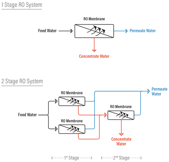
In a one stage RO system, the feed water enters the RO system as one stream and exits the RO as either concentrate or permeate water.
In a two-‐stage system the concentrate (or reject) from the first stage then becomes the feed water to the second stage. The permeate water is collected from the first stage is combined with permeate water from the second stage. Additional stages increase the recovery from the system.
Array
In a reverse osmosis system, an array describes the physical arrangement of the pressure vessels in a 2-stage system. Pressure vessels contain RO membranes (usually from 1 to 6 RO membranes are in a pressure vessel). Each stage can have a certain amount of pressure vessels with RO membranes. The reject of each stage then becomes the feed stream for the next successive stage. The 2 stage RO system displayed on the previous page is a 2:1 array which means that the concentrate (or reject) of the first 2 RO vessels is fed to the next 1 vessel.
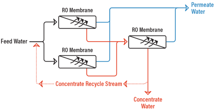
RO System with Concentrate Recycle
With an RO system that cannot be properly staged, and the feed water chemistry allows for it, a concentrate recycle setup can be utilized where a portion of the concentrate stream is fed back to the feed water to the first stage to help increase the system recovery.
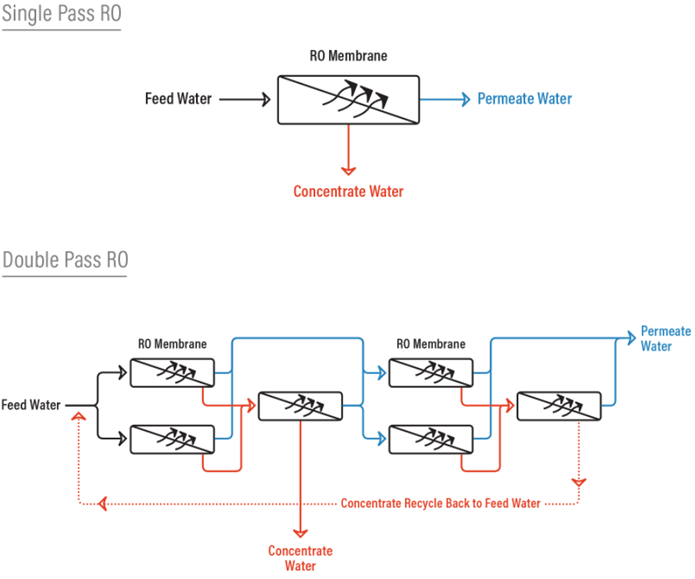
Single Pass RO vs Double Pass RO
Think of a ‘pass’ as a standalone RO system. The difference between a single pass RO system and a double pass RO system is that with a double pass RO, the permeate from the first pass (first RO) becomes the feed water to the second pass (or second RO) which ends up producing a much higher quality permeate because it has essentially gone through two RO systems.
Besides producing a much higher quality permeate, a double pass system also allows the opportunity to remove carbon dioxide gas from the permeate by injecting caustic between the first and second pass. C02 is undesirable when you have mixed bed ion exchange resin beds after the RO. By adding caustic after the first pass, you increase the pH of the first pass permeate water and convert C02 to bicarbonate (HCO -‐) and carbonate (CO ‐2) for better rejection by the RO membranes in the second pass. This can’t be done with a single pass RO because injecting caustic and forming carbonate (CO ‐2) in the presence of cations such as calcium will cause scaling of the RO membranes.
RO Pretreatment
Proper pretreatment using both mechanical and chemical treatments is critical for an RO system to prevent fouling, scaling and costly premature RO membrane failure and frequent cleaning requirements. Below is a summary of common problems an RO system experiences due to lack of proper pretreatment.
Fouling
Fouling occurs when contaminants accumulate on the membrane surface effectively plugging the membrane. There are many contaminants in municipal feed water that are naked to the human eye and harmless for human consumption, but large enough to quickly foul (or plug) an RO system. Fouling typically occurs in the front end of an RO system and results in a higher pressure drop across the RO system and a lower permeate flow. This translates into higher operating costs and eventually the need to clean or replace the RO membranes. Fouling will take place eventually to some extent given the extremely fine pore size of an RO membrane no matter how effective your pretreatment and cleaning schedule is. However, by having proper pretreatment in place, you will minimize the need to address fouling related problems on a regular basis.
Fouling can be caused by the following:
- Particulate or colloidal mater (dirt, silt, clay)
- Organics (humic/fulvic acids)
- Microorganisms (bacteria, etc.). Bacteria present one of the most common fouling problems since RO membranes in use today cannot tolerate a disinfectant such as chlorine and therefore microorganisms are often able to thrive and multiply on the membrane surface. They may produce biofilms that cover the membrane surface and result in severe biofouling.
- Breakthrough of filter media upstream of the RO unit. GAC carbon beds and softener beds may develop an under-drain leak and if there is not adequate post filtration in place the media can foul the RO membranes.
By performing analytical tests, you can determine if the feed water to your RO has a high potential for fouling. To prevent fouling of an RO system, mechanical filtration methods are used. The most popular methods to prevent fouling are the use of multi-‐media filters (MMF) or microfiltration (MF). In some cases, cartridge filtration will suffice.
Scaling
As certain dissolved (inorganic) compounds become more concentrated (remember discussion on concentration factor) then scaling can occur. If these compounds exceed their solubility limits, then they can precipitate on the membrane surface as scale. The results of scaling are a higher pressure drop across the system, higher salt passage (less salt rejection), and low permeate flow. An example of a common scale that tends to form on an RO membrane is calcium carbonate (CaCO3).
Chemical Attack
Modern thin film composite membranes are not tolerant to chlorine or chloramines. Oxidizers such as chlorine will ‘burn’ holes in the membrane pores and can cause irreparable damage. The result of chemical attack on an RO membrane is a higher permeate flow and a higher salt passage (less salt rejection).
Therefore, microorganism growth on RO membranes tends to foul RO membranes so easily since there is no biocide present to prevent its growth.
Mechanical Damage
Part of the pretreatment scheme should involve pre and post RO system plumbing and controls. If ‘hard starts’ occur mechanical damage to the membranes can occur. Likewise, if there is too much backpressure on the RO system then mechanical damage to the RO membranes can also occur. These can be addressed by using variable frequency drive motors to start high pressure pumps for RO systems and by installing check valve(s) and/or pressure relief valves to prevent excessive back pressure on the RO unit that can cause permanent membrane damage.
Pretreatment Solutions
Below are some pretreatment solutions for RO systems that can help minimize fouling, scaling and chemical attack.
Multi-Media Filter (MMF)
A Multi-Media Filter is used to help prevent fouling of an RO system. A MMF typically contains three layers of media consisting of anthracite coal, sand, and garnet, with a supporting layer of gravel at the bottom. These are the medias of choice because of the differences in size and density. The larger (but lighter) anthracite coal will be on top and the heavier (but smaller) garnet will remain on the bottom. The filter media arrangement allows the largest dirt particles to be removed near the top of the media bed with the smaller dirt particles being retained deeper and deeper in the media. This allows the entire bed to act as a filter allowing much longer filter run times between backwashes and more efficient particulate removal.
A well-‐operated Multi-Media Filter can remove particulates down to 15-‐20 microns. A Multi-Media Filter that uses a coagulant addition (which induces tiny particles to join to form particles large enough to be filtered) can remove particulates down to 5-‐10 microns. To put this in perspective, the width of a human hair is around 50 microns.
A multi-media filter is suggested when the Silt Density Index (SDI) value is greater than 3 or when the turbidity is greater than 0.2 NTU. There is no exact rule, but the above guidelines should be followed to prevent premature fouling of RO membranes.
It is important to have a 5-micron cartridge filter placed directly after the MMF unit if the under drains of the MMF fail. This will prevent the MMF media from damaging downstream pumps and fouling the RO system.
Microfiltration (MF)
Microfiltration is effective in removing colloidal and bacteria matter and has a pore size of only 0.1 – 10µm. MF is helpful in reducing fouling potential for an RO unit. Membrane configuration can vary between manufacturers, but the “hollow fiber” type is the most used. Typically, the water is pumped from the outside of the fibers, and the clean water is collected from the inside of the fibers.
Microfiltration membranes used in potable water applications usually operate in “dead-‐end” flow. In dead-‐end flow, all of the water fed to the membrane is filtered through the membrane. A filter cake that must be periodically backwashed from the membrane surface forms. Recovery rates are normally greater than 90 percent on feed water sources which have high quality and low turbidity feeds.
Antiscalants/Scale Inhibitors
Antiscalants and scale inhibitors, as their name suggests, are chemicals that can be added to feed water before an RO unit to help reduce the scaling potential of the feed water. Antiscalants and scale inhibitors increase the solubility limits of troublesome inorganic compounds. By increasing the solubility limits, you can concentrate the salts further than otherwise would be possible and therefore achieve a higher recovery rate and run at a higher concentration factor. Antiscalants and scale inhibitors work by interfering with scale formation and crystal growth. The choice of antiscalant or scale inhibitor to use and the correct dosage depends on the feed water chemistry and RO system design.
Water Softening
A water softener can be used to help prevent scaling in an RO system by exchanging scale forming ions with non-scale forming ions. As with a MMF unit, it is important to have a 5-micron cartridge filter placed directly after the water softener if the under drains of the softener fail.
Sodium Bisulfite
By adding sodium bisulfite (SBS or SMBS), which is a reducer, to the water stream before an RO at the proper dose you can remove residual chlorine and chloramines.
Granular Activated Carbon (GAC)
GAC is used for both removing organic constituents and residual disinfectants (such as chlorine and chloramines) from water. GAC media is made from coal, nutshells, or wood. Activated carbon removes residual chlorine and chloramines by a chemical reaction that involves a transfer of electrons from the surface of the GAC to the residual chlorine or chloramines. The chlorine or chloramines ends up as a chloride ion that is no longer an oxidizer.
The disadvantage of using a GAC before the RO unit is that the GAC will remove chlorine quickly at the very top of the GAC bed. This will leave the remainder of the GAC bed without any biocide to kill microorganisms. A GAC bed will absorb organics throughout the bed, which is potential food for bacteria, so eventually a GAC bed can become a breeding ground for bacteria growth which can pass easily to the RO membranes. Likewise, a GAC bed can produce very small carbon fines under some circumstances that have the potential to foul an RO. A cartridge filter should be placed after a GAC and before an RO to protect membranes from carbon fines.
RO Data Trending and Normalization
The RO membranes are the heart of the RO system and certain data points need to be collected to determine the health of the RO membranes. These data points include the system pressures, flows, quality, and temperature. Water temperature is directly proportional to pressure. As the water temperature decreases it becomes more viscous and the RO permeate flow will drop as it requires more pressure to push the water through the membrane. Likewise, when the water temperature increases the RO permeate flow will increase. As a result, performance data for an RO system must be normalized so that flow variations are not interpreted as abnormal when no problem exists. The normalized flows, pressures and salt rejection should be calculated, graphed and compared to the baseline data (when the RO was commissioned or after the membranes were cleaned or replaced) to help troubleshoot any problems and also determine when to clean or inspect the membranes for damage. Data normalization helps display the true performance of the RO membranes. As a rule of thumb, when the normalized change is +/‐ 15% from the baseline data then you need to investigate the cause and clean the membranes.
RO Cleaning
RO membranes will inevitably require periodic cleaning, anywhere from 1 to 4 times a year depending on the feed water quality. As a general rule, if the normalized pressure drops or the normalized salt passage has increased by 15%, then it is time to clean the RO membranes. If the normalized permeate flow has decreased by 15% then it is also time to clean the RO membranes. You can either clean the RO membranes in place (if equipped) or have them removed from the RO system and cleaned off site by a service company that specializes in this service. It has been proven that offsite membrane cleaning is more effective at providing a better cleaning than onsite cleaning skids.
RO membrane cleaning involves low and high pH cleaners to remove contaminants from the membrane. Scaling is addressed with low pH cleaners and organics, colloidal and biofouling are treated with a high pH cleaner. Cleaning RO membranes is not only about using the appropriate chemicals. There are many other factors involved such as flows, water temperature, water quality, properly designed and sized cleaning skids, and many other factors that an experienced service group must address to properly clean RO membranes.
Summary
Reverse Osmosis is an effective and proven technology to reduce water contaminants. Further post treatment after the RO system such as mixed bed deionization can increase the quality of the RO permeate and make it suitable for the most demanding applications. Proper pretreatment and monitoring of an RO system is crucial to preventing costly repairs and unscheduled maintenance. With the correct system design, maintenance program, and experienced service support, your RO system should provide many years of high purity water.